NMBS TRAIN STATION CANOPY
The project for the covering of the railway station in Leuven (Belgium) is part of a global project for the renovation of the existing station and its surroundings.
As prologue, a master plan was elaborated to reduce the surface intake of the railway infrastructure, leading, after the completion of the new railway scheme, into the urbanisation of the land formerly occupied by the tracks. The global project was developed within the guidelines of the Spatial Structure Plan of Flanders (Northern part of Belgium), a regional plan which defines the Leuven station as a first category station in the Flemish railway network.
The importance of the existing station building within the redevelopment of the neighbourhood was recognised by the commissioner of the new station project, the Nationale Maatschappij der Belgische Spoorwegen (National Belgian Railways Company), since the early stages of the project. Most valued are its following meanings: its great emotional significance for the inhabitants and for the travellers, and its function as a link between the traffic streams as well as between the form and functions of the buildings that will be erected nearby in the future.
In this context, a limited international competition for the design of a new canopy over the platforms was conducted in two stages. From the 18 design teams originally submitting, 6 were selected (alphabetical order): De Smet Vermeulen architecten, Luscher Architectes, Nicholas Grimshaw & Partners, Richard Rogers, Samyn and Partners, and Santiago Calatrava. The design by Samyn and Partners was chosen on April 4th 2000.
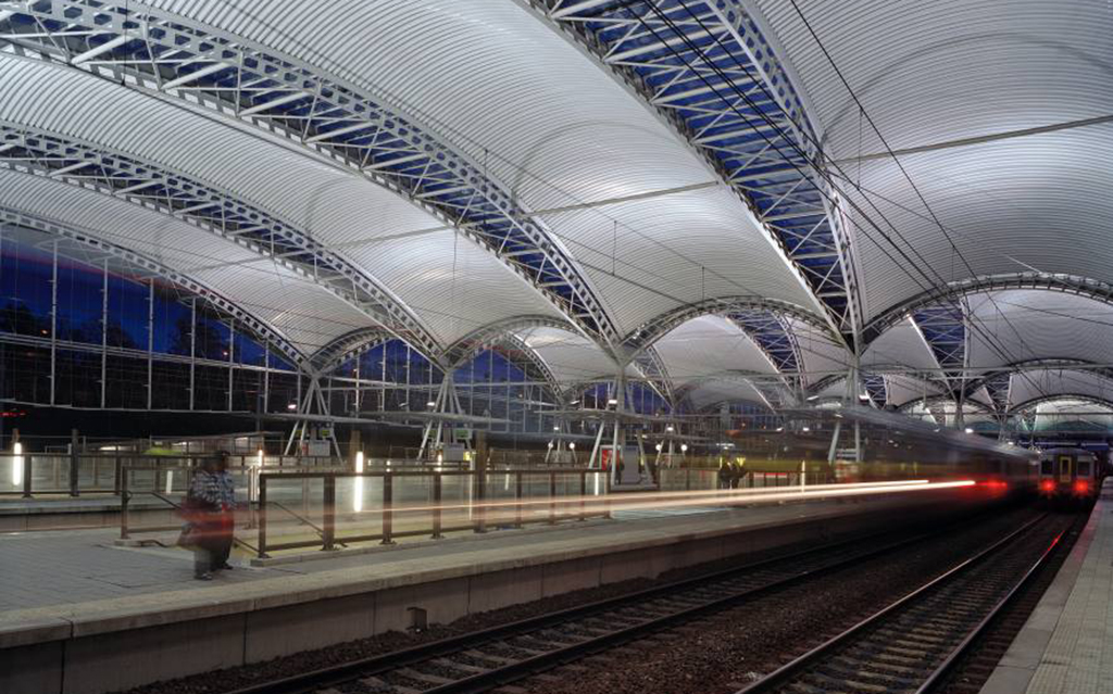
The Canopy
The canopy was designed with respect to the scale of the neighbouring buildings. From the observation of the existing discontinuity between the surrounding townparts, its design aims to link both physically and symbolically the inner city of Leuven with the suburban town Kessel-Lo situated on the opposite side of the tracks, an intention also carried by the covered pedestrian bridge, and to bind together the new and existing parts of the global station project.
The composition seeks to offer maximum comfort for the travellers: sheltering from wind and rain, abundance of daylight, easy readability of the functions and of the numerous signs, acoustic absorption of the traffic noise, etc.
The recyclability, easy assembly and dismantlement of the components are carefully taken into account, along with their durability and easy maintenance.
In an ecological perspective, optimal use of the matter is sought in the structural principles in order to achieve load bearing with minimal dead weight.
The primary structure
The primary structure of the platform canopy rests on 25 tubular piles made of four inclined columns in the central part of the canopy, and three inclined columns on its perimeter where the loads are asymmetrical. The inclined columns meet at 7m13 above the level of the rails. The supports of the high voltage cables are attached to the piles at their junction.
The supports are located at the intersection of two perpendicular series of 5 axis. The longitudinal axis, 14.54m apart, follow the spacing of the railtracks. The transversal axis, respectively 52m, 39m, 39m and 52m apart, follow the cadence of the high voltage cables.
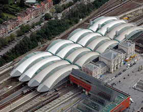
The symmetry axis of the structure is centered on the rear elevation of the existing station building.
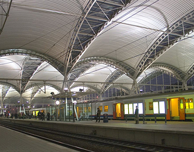
Springing from the piles, the primary structure of the canopy consists in twenty longitudinal parabolic twin steel arches. Each arch is composed of worked HEA-section. The sections are cut in half longitudinally and pre-bent in the workshop. The pre-bent half-sections are connected with welded steel plates of variable height (30 tot 50cm) in response to the variation of the strains alongside the span. On site, the twin arches are set symmetrically at an angle of 17°10′ with the vertical plane of the supports, and joined every 3,25m to increase their lateral stiffness.
The lateral forces sustained by the parabolic arches are transferred transversally by regularly spaced pairs of tie-beams. On the sides, the horizontal forces are converted into vertical forces, supported by a vertical structure which also carries the suspended lateral facades.
Arches being nearly as flexible as optimised lattice-trusses under evenly distributed vertical loads, and their form adapting easily to thermal movement without causing important additional strains, the metal structure is designed so that movement, expansion and contraction under the material itself. In this manner, no superfluous amount of material is wasted to stiffen the structure more than required by the loads.
The secondary structure and cover
A parabolic pre-formed steel decking spans transversally between the primary arches, supporting the insulation and the aluminium roof cladding. To prevent undercooling condensation, the insulation is pressed between the steel decking and the profiled aluminium stripes.
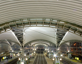
Stretching in between the vaults over each set of twin arches, glazed lens-shaped openings provide natural daylight. Longitudinally, the space between two consecutive vaults is left open for natural ventilation. Lowered glass roofs that “float” below the steel decking with a short overlap insure sheltering while maximising light intake.
In case of fire, the smoke is entrapped by the vaults and exhausts through the ventilation openings. The vaulted shape of the roof also entraps the turbulent roaring of the trains into the perforated steel decking (30%), insuring acoustic comfort to the travellers supports.
The extremities of the canopy are made of expanded steel sheets, which reduces the air turbulences of incoming or passing trains, as well as the influence of wind on the structure. The fact that the openings in the head facades are minimised in such a way has a particularly favourable influence on the microclimate underneath the canopy.
At each pile and alongside the lateral facades, additional glazed awnings were designed to the travellers’ scale, reflecting the light towards the vaults.
They accommodate various equipments and allow flexible addition as required by future needs.
The footbridge
In answer to the continuity and discontinuity issue, a wood-surfaced steel footbridge and a pedestrian underground walkway connect the two station banks, guiding the traffic effortlessly from one part of town to the other. The 7m wide footbridge is divided into a pedestrian- and a bicycle-lane.
As large lanterns posted on the platforms, five glazed lift shafts draw the daylight through the canopy into the covered space, literally setting the footbridge into the spotlight. They are echoed at both ends of the platforms by five transparent blue glass boxes which provide sheltered space for the end-passengers, and act as landmarks to announce the arrival into, and departure from the station. At night, all fifteen lanterns are brightly lit.
Photo credits: M-F. Plissart, J. Deconinck
1869 Projects

